Spend more time on actual design work and not on remedial tasks.
The add-in myCADtools, is a set of forty plus (40+) API macros that have been developed with the goal to increase your productivity in SOLIDWORKS by making tasks that are very time-consuming, much faster. This is to ensure more time is spent on actual design work and not on remedial tasks such as the bulk creation of drawings or modification and creation weldment cutlists to name a few.
myCADtools is fully integrated into your SOLIDWORKS environment and is available to all our subscription customers for free for the first year as a benefit of being a MECAD customer.
To access your myCADtools in SOLIDWORKS you use the following process:
Figure 1: Where to find myCADtools?
Now there are a number of scenarios that I would like to address:
Scenario 1: The bulk creation of standard drawings
Normally when creating drawings in SOLIDWORKS, you would tend to do your general 3D modelling in the part or assembly environment and then create a drawing from there. However, to go back and create a drawing per part can be tedious and incredibly time consuming, whether it is done one by one after each part is created or right at the end of the design process where the production drawings are now required for the manufacturing floor.
I will let you think on how much time you spend creating drawings, however, below is a quick example of the time you could spend creating two (2) basic drawings with some predefined views and your model item dimensions: Total time spent: +- 1 Minute
Figure 2: Manual Drawing Creation
Now let me introduce you to the first tool we will be addressing today: SmartDrawings
SmartDrawings is a tool that allows you to create any number of drawings depending on the type of drawing you require, Part, Assembly, Sheetmetal or Weldment. You are able to specify a specific template for each drawing type ensuring consistency throughout your drawings. Giving the tool a form of naming conventions you want all your drawings to have allows for further consistency and simply by adding either the “ACTIVE” SOLIDWORKS window (i.e. the model that is currently open) or by specifying a file or even a folder location where the models reside and selecting Apply the tool will run and create your drawings for you.
As mentioned, there are additional features that can be included depending on the drawing type such as specific dimension types, i.e. Model Items where you can choose from the standard Model Items dimension types. Centerlines, Balloons, and your different table types, such as standard Bill of Materials (BOM), Weldment Cutlists and Revision tables can be added to any drawing created by the tool according to again a specified table template.
All in all, SmartDrawings allows for a consistent drawing creation tool which means less time will be spent on the creation of your drawings and more time spent on the design aspect. Whilst we are claiming this can do all of the above-mentioned wonderful things – there might be a few tweaks that are required by yourself; however, the bulk of the work is completed for you.
Below is a video of the tool creating thirty-eight (38) drawings with some predefined views and model item dimensions:
Total time spent: +- 4 Minutes – that is equivalent of 9.5 drawings per minute!
Figure 3: Smart Drawings
Scenario 2: Optimisation of Cutlists
Have you ever thought about the ways in which you could minimise waste in your workshop, especially when you are working with multiple different beam lengths? Now yes, you have your cutlists according to your models but how does this affect your stock and how it’s cut to length? What about your “scrap” that you have leftover – often it can be faster cutting new stock items than having to work out what scrap you can or cannot use.
Generally this is a manual process of measuring out the lengths, calculating the number of stock items required and someone on the workshop floor needs to ensure that it is cut correctly with the correct stock items. This can be a fairly long and sometimes inaccurate process.
With myCADtools – you have access to a tool called: Cutting Optimisation
Cutting Optimisation allows you to do exactly as I described above all from within your SOLIDWORKS.
What is required?
- A Weldment Cutlist in a drawing
- A few minutes of your time to generate the report and configure the tool.
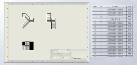
Figure 4: Drawing of a Weldment Multi-body part with a Weldment Cutlist
This tool allows you to generate a cutting optimisation report where all information pertaining to the different beams is shown as well as a calculated optimal way of using the stock and scraps that you have available to ensure minimal wastage with even a consideration of your blade sizing on your machine. All segments are colour coded for easy referencing and are split into sections on a per profile basis.
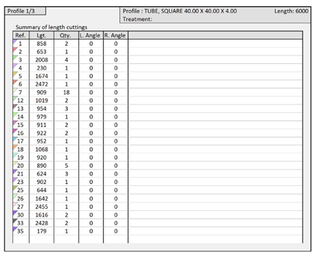 Figure 5: Cutting Summary
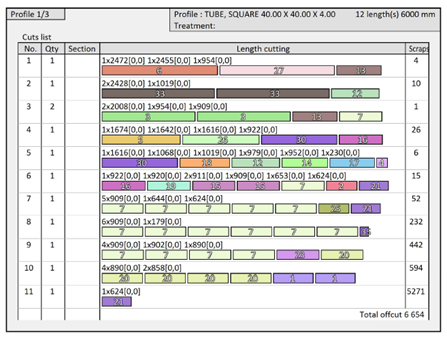
Figure 6: Cutting Optimisation Breakdown
Figure 7: Cutting Optimisation Setup
Scenario 3: Standardisation of your CAD files
Ensuring that all your CAD data is of a specific standard is very important to ensure, one, the cleanliness of your data and two the consistency of all your CAD data across your design office. Now we all know the woes of “Legacy” data that might have been done before a CAD standard was implemented or by another user who might have had a different way of thinking when it comes to your standards.
To manually rectify and make all this data consistent is no easy task, the example I am going to use today is a way of standardising your MASS unit of measure for all files that are run through the tool. Note this does not change the actual sizing of the data – merely the standard units that are associated to the file. This is but one example of many capabilities of this particular tool.
With myCADtools – you have access to a tool called: Integration
Integration is the tool that will allow you to standardise your files once off with a single use of this tool. Once setup this tool uses conditions and operations to determine which rule to follow and will execute certain operations according to the conditions.
I.e. IF the file is a SOLIDWORKS part file OR SOLIDWORKS assembly file, CHANGE the mass from (x) to KG.
Figure 8: Integration Tool
For further information on any of these tools – please visit the myCADtools playlist on our YouTube channel. Or visit our myCADtools webpage.
If you are a subscription customer and would like to benefit from any of the tools mentioned above or in the YouTube playlist, please give our offices a call. We will be happy to assist with installations of myCADtools as well as a brief explanation to get your started on your myCADtools journey!


.png "Reseller")